
Note
This is my page about USB-IR-BOY. My original works are PCBs and schematics in Eagle for USB-IR-BOY and PROMMER.
You can find it here:
http://www.pavolmaria.org/elektronika/usbirboy/index_en.php?id=pcb
The original USBIRBOY page is locatede on address http://usbirboy.sourceforge.net/.
USB-IR-Boy Board
Part list
- one 20pin PDIP case Motorola MC68HC908JB8 (Part code: MC68HC908JB8JPE)
- one 10MOhm resistor
- one 6Mhz crystal
- two 22pF condensators
- one TSOP1738 (or compatible IR receiver e.g. SFH506-38)
Unvalued parts
- R1 -- 110 - 162kOhm for voltage deviation to MCU pin (100k
gives about 4V and 162k about 2.4)
I use 110k to get about 3.6V (This depends on Vcc, reference is 5V as it sould be) - C1 -- Condensator to stabilize the USB provided power. (reception
of the TSOP is poor if this is missing)
This sould be as big as possible. I use 100nF (This sould be located near power pins of TSOP)
Electronic schematic
Following image represents the
electronic schematic of the USB-IR-Boy device board.
In the schematic, there is optional regulator sircuit to be used if you would like to use higher voltage than 5V as the source voltage of the board.
There is also optional LED connected to PTA0 that in the MCU code are toggled on and off during the execution of the program. This led can be used to ensure your sircuit is working, operational and software is running inside.

Created with gEda
Some points
- Vcc is 5V (provided from USB connector)
- R1 resistor is there to make voltage deviation from 5V to
MCU 3.3V. TSOP1738 has internal pullup resistor of 80kOhm between the
pin 3 and Vcc.
- MCU PTA,RST,PTD0/1 and IRQ pins are "in the air" due there are
internal pullups
- There is no resistor between MCU D- and Vdd pins due there is internal resistor (enabled by usb_init function )
- USB internal power source can be used but it might degrease the
sensibility of the TSOP due the strinct operating
voltage stability it needs.
- USB PWR and USB connectors can be choosed separately or using
same connector depending on board layout.
There is also standard USB connectors that can be used but they are not needed for home use. ( Some say this is adviced due it makes USB side of the system more stabile )
"Test" board layout
Following image
represents example design using ready test board.
Please see pictures sction for implemented board using this layout.
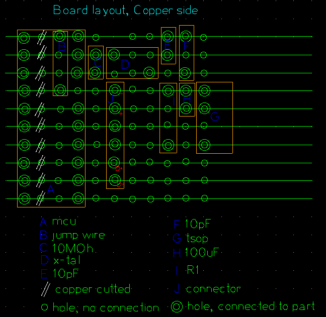
Notes:
- Picture is from copper side of the board
- MCU pin 20 is in picture upper left corner
- MCU ping 4 is not connected to the board (Chip support pin 4 is cutted so it does not reach the copper side of the board)
Please see pictures sction for implemented board using this layout.
Notes:
- Picture is from copper side of the board
- MCU pin 20 is in picture upper left corner
- MCU ping 4 is not connected to the board (Chip support pin 4 is cutted so it does not reach the copper side of the board)