Note
This is my page about USB-IR-BOY. My original works are PCBs and schematics in Eagle for USB-IR-BOY and PROMMER.
You can find it here:
http://www.pavolmaria.org/elektronika/usbirboy/index_en.php?id=pcb
The original USBIRBOY page is locatede on address http://usbirboy.sourceforge.net/.
USB-IR-Boy Prommer
Part list
- one 16pin PDIP case Maxim RS232
- four 10kOhm resistors
- one 10MOhm resistor
- one 2.2kOhm resistor
- one 6Mhz crystal
- two 22pF condensators
- four 100nF condensators
- one fast diode (dont think it matters what type)
- RS232 connector
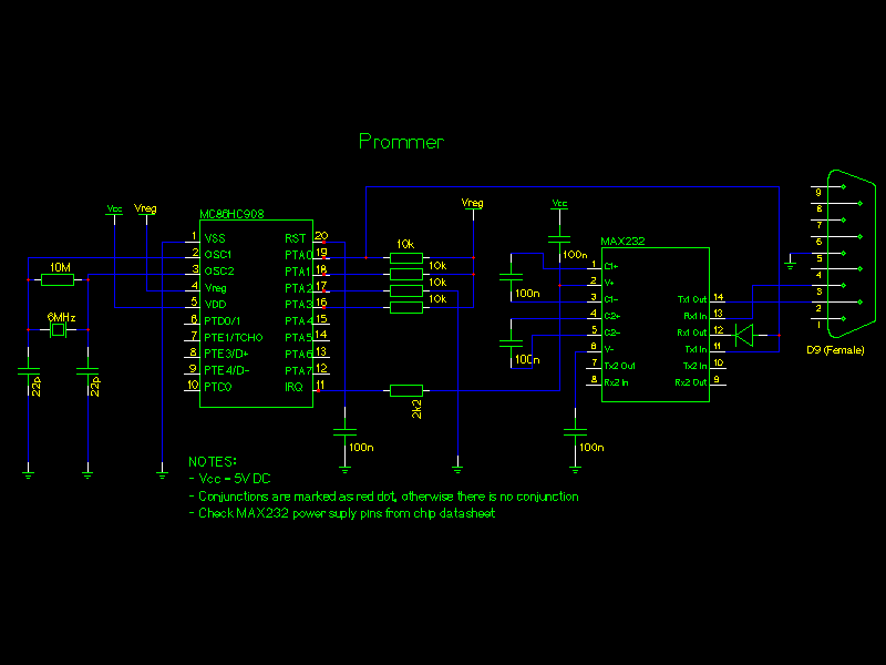
Electronic schematic
Following electronic schematic
represents the home made prommer that we have been using to program the
MCU.
In the schematic, there is optional regulator sircuit to be used if you would like to use higher voltage than 5V as the source voltage of the board.

Created with gEda
Last modified date: Thu 01.01.1970 01:00:00 In the schematic, there is optional regulator sircuit to be used if you would like to use higher voltage than 5V as the source voltage of the board.

Created with gEda
Some points
- Vcc is 5V
- Vreg is 3.3V reguladed by MCU
- MAX232 power pins are not shown in the schematic due the way gEda
handles default chip power pins.
( VCC=pin 16, Gnd=pin 15)
